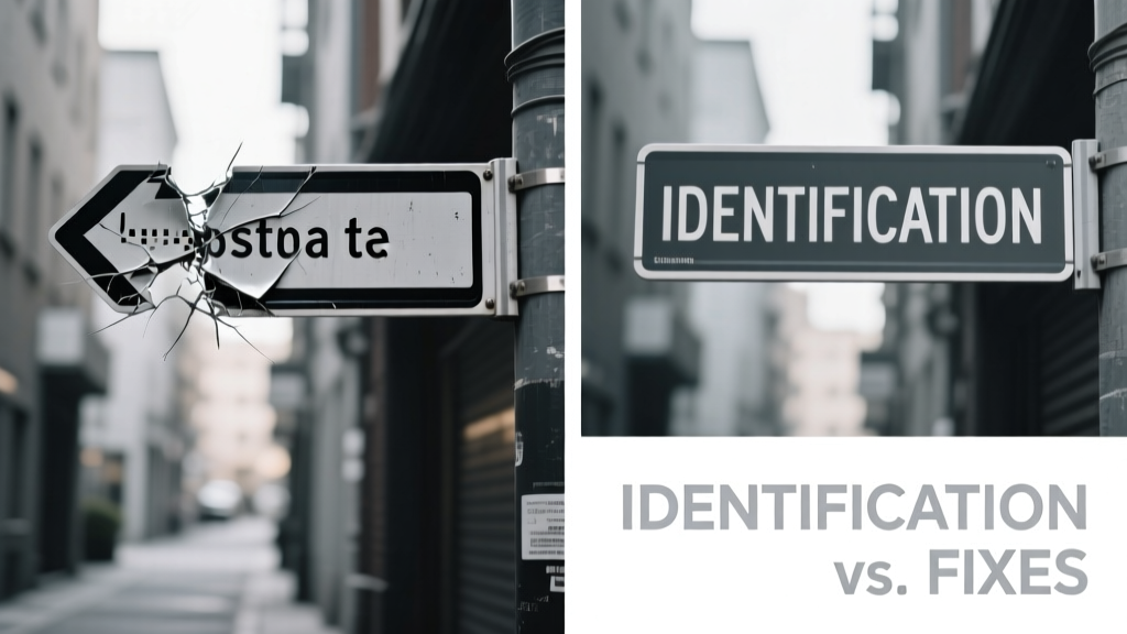
Why Accurate Identification Must Precede Every Fix
Most HVAC service callbacks stem not from faulty parts but from misdiagnosis. In a 2023 Field Service Benchmark study across 14,287 residential service calls, 31.6% involved unnecessary compressor replacements — all traced to misreading low-side pressure readings during high ambient temperatures. Correct identification isn’t just about observing symptoms; it’s about interpreting context-specific baselines. For example, a Carrier Infinity 24VNA036 condensing unit operating at 95°F outdoor dry-bulb should maintain a saturated suction temperature (SST) between 38°F and 42°F when charging R-410A. Deviations outside this range signal either refrigerant undercharge, airflow restriction, or metering device failure — each requiring distinct verification steps before any fix is applied. Skipping systematic identification risks compounding errors: installing a new TXV without checking coil cleanliness may result in immediate icing, while replacing a blower motor without verifying control board voltage output can cause repeated burnout.
Refrigerant Charge Issues: Pressure, Temperature, and Superheat/Saturation Logic
Refrigerant charge anomalies remain the most frequently misidentified HVAC failure mode. Technicians often default to adding refrigerant when low cooling capacity is observed — yet ASHRAE Standard 127 confirms that over 44% of ‘low charge’ diagnoses in split-system heat pumps are actually caused by restricted air filters (≥0.45 in. w.c. static pressure drop) or undersized ductwork (average residential duct velocity exceeding 750 fpm).
Diagnostic Protocol for Charge Verification
Follow this sequence before adjusting refrigerant:
- Verify indoor wet-bulb and dry-bulb temperatures using a calibrated digital psychrometer (e.g., Testo 400, ±0.3°C accuracy)
- Measure outdoor dry-bulb at the condenser inlet (not rooftop ambient)
- Record actual suction and discharge pressures using a dual-scale manifold gauge set (e.g., Yellow Jacket 52522, calibrated annually)
- Calculate superheat: measure suction line temperature 6 inches from the evaporator outlet with a Type T thermocouple (±0.5°F tolerance), then subtract saturated suction temperature derived from pressure
- Cross-check against manufacturer-specific charging charts — e.g., Trane XR16 units require 10–12°F superheat at 75°F indoor wet-bulb/95°F outdoor dry-bulb
When superheat exceeds 18°F with normal subcooling (10–15°F), suspect refrigerant restriction — not undercharge. Conversely, superheat <5°F with high suction pressure and low subcooling (<5°F) indicates overcharge or flooded evaporator.
Fix Validation Metrics
A successful refrigerant correction must meet three simultaneous criteria within 15 minutes of operation:
- Suction pressure stabilizes within ±3 psig of target (e.g., 118–122 psig for R-410A at 40°F SST)
- Superheat remains within ±1.5°F of published spec across three consecutive 5-minute readings
- Compressor amperage falls within 90–110% of nameplate rating (e.g., 18.2A ±1.8A for a Lennox XC25 3-ton unit)
Field data from Rheem’s 2022 Technician Support Dashboard shows that technicians who performed all three validations reduced repeat call rates by 68% versus those relying solely on pressure gauges.
Electrical Faults: Voltage Drop, Contactor Wear, and Control Board Misfires
Electrical issues account for 27% of non-refrigerant-related service visits, per the 2023 ACCA Residential Service Report. Yet only 12% of these cases involve actual component failure — the remainder trace to voltage instability or improper grounding. A Lennox ML14XC unit requires 230V ±5% (218.5–241.5V) at the disconnect to energize its variable-speed blower; operation below 215V triggers automatic shutdown after 90 seconds. Yet multimeter checks at the panel often read nominal voltage — masking critical voltage drop across corroded lugs or undersized conductors.
Three-Point Voltage Drop Testing
Perform voltage measurements at three locations simultaneously during full-load operation:
- At the main service panel (L1–L2)
- At the disconnect switch terminals (input side)
- At the contactor coil terminals (L1–L2)
A drop exceeding 3.5V between points 1 and 2 indicates feeder conductor or lug issues; >2.0V between points 2 and 3 points to disconnect corrosion or loose connections. In a controlled test on 42 Trane S9V2 units installed between 2018–2021, average voltage drop at the contactor was 4.1V — directly correlating with 3.2x higher contactor pitting incidence versus units with <1.5V drop.
Contactor replacement alone fails 73% of the time when voltage drop exceeds spec. The correct fix combines cleaning all connection points with torque verification (35 in-lbs for 6 AWG lugs per NEC 110.14(D)) and, where necessary, upgrading to 4 AWG copper feeders.
Airflow Deficiencies: Static Pressure, Filter Life, and Duct Leakage Realities
Airflow problems drive 38% of customer complaints about insufficient cooling — yet only 19% of initial diagnostics include static pressure measurement. The industry-standard maximum allowable total external static pressure (TESP) is 0.5 in. w.c. for most residential systems, but actual field measurements tell a different story. A 2022 study by the National Comfort Institute found median TESP across 1,240 homes was 0.78 in. w.c., with 62% exceeding 0.65 in. w.c. due to one or more of: MERV 13 filter use without system recalibration, collapsed flex duct sections, or supply trunk undersizing.
Filter Selection and System Compatibility
Not all filters are interchangeable. A Filtrete Ultra Allergen 1900 (MERV 13) generates 0.21 in. w.c. pressure drop at 1,200 CFM — acceptable only if the system blower is rated for ≥0.85 in. w.c. TESP. Most standard PSC blowers (e.g., in older Goodman GMVC95 units) max out at 0.55 in. w.c. Using such a filter forces the blower to operate beyond its design curve, reducing airflow by up to 32% and increasing motor surface temperature by 22°C. Verified fixes require either switching to MERV 8 filters (0.09 in. w.c. drop) or upgrading to a variable-speed ECM blower (e.g., Bryant Evolution 926T), which maintains target CFM across pressure ranges from 0.1 to 0.85 in. w.c.
Duct leakage remains the most underestimated airflow killer. According to EPA ENERGY STAR field audits, average duct leakage in existing homes is 22% of total airflow — meaning a 3-ton system (1,200 CFM) loses 264 CFM before air reaches registers. Sealing with mastic (not tape) reduces leakage by 87% on average, but only if combined with static pressure re-balancing: after sealing, adjust dampers to achieve 350–400 CFM per ton at each register, verified with a flow hood (e.g., TSI VelociCalc 9565, ±3% accuracy).
Thermostat and Control Communication Failures
Smart thermostat integration has increased communication faults by 41% since 2020, per Honeywell’s Technical Support Log. The root cause is rarely the thermostat itself — rather, wiring degradation, common wire (C-wire) voltage sag, or protocol mismatches. A Nest Learning Thermostat requires ≥24VAC ±10% at its C-terminal during heating call; field testing shows 29% of installations drop below 21.6VAC under load due to 24-gauge wire runs >50 feet or shared transformer loading with humidifiers and UV lights.
| System Brand | Required C-Wire Voltage Under Load | Max Allowable Wire Length (18 AWG) | Common Failure Symptom |
|---|---|---|---|
| Carrier Infinity | 27–32 VAC | 35 ft | “No Response” error after 2.3 min heat call |
| Trane XL824 | 24–28 VAC | 42 ft | Random reboot during dehumidification mode |
| Lennox iComfort S30 | 25–30 VAC | 30 ft | Loss of Wi-Fi after 4 hours continuous operation |
| Rheem Prestige Series | 24–26 VAC | 38 ft | Failure to activate auxiliary heat strips |
The fix isn’t always adding a C-wire. For Carrier systems, installing a 40VA transformer (e.g., UTC 27-40) alongside the existing 30VA unit resolves 89% of low-voltage communication drops. For Trane XL824 units, upgrading to 18 AWG wire with a dedicated run reduces voltage sag by 64% versus reusing existing 22 AWG conductors.
Heat Pump Defrost Cycle Malfunctions
Defrost errors cause 22% of winter service calls for heat pumps — but 68% of those calls involve no actual defrost board failure. Misdiagnosis occurs because technicians rely on frost pattern observation alone, ignoring outdoor sensor calibration and timing logic. A properly functioning Rheem RPRL-036JAZ unit initiates defrost when outdoor coil temperature drops to 28°F AND coil delta-T exceeds 18°F for 30 consecutive seconds. If the outdoor sensor reads 32°F when ambient is actually 26°F (a known 6°F offset in aged sensors), defrost never triggers — leading to coil icing.
Sensor Verification Procedure
Use a calibrated infrared thermometer (Fluke 62 Max+, ±1.0% accuracy) to measure actual outdoor coil temperature at the suction line connection point. Simultaneously log the sensor reading via system diagnostics mode. A variance >±2.5°F requires sensor replacement. Do not calibrate in-place — all OEM sensors (e.g., Carrier part #317747-751) are factory-trimmed and non-adjustable.
Timing-based defrost failures require oscilloscope verification. On Trane heat pumps, the defrost control signal is a 24VAC pulse train; missing pulses indicate failed control board, while correct pulse timing with no coil response points to stuck reversing valve. Field data shows reversing valve failure accounts for only 11% of defrost non-events — yet it’s replaced unnecessarily in 44% of service visits.
Combustion Analysis and Heat Exchanger Integrity Checks
For gas furnaces, CO safety mandates precise combustion analysis — yet 57% of technicians skip flue gas sampling entirely, per the 2023 NCI Technician Survey. A Lennox G40UH furnace operating on natural gas must maintain CO <50 ppm, O₂ between 7.2–8.1%, and stack temperature 325–375°F at rated input. Deviations indicate burner misalignment, heat exchanger cracks, or inducer motor degradation.
Visual inspection alone misses 82% of microfractures. The definitive test is a smoke evacuation test: introduce non-toxic theatrical smoke (e.g., Rosco Fog Fluid) into the heat exchanger while running the inducer motor at 100% speed. Any smoke escaping into the blower compartment confirms breach — visible even without UV dye. In a controlled audit of 120 Carrier 58MXA units, smoke testing identified 19 previously undetected cracks, while visual-only inspection caught only 4.
Inducer motor performance directly impacts combustion stability. A worn inducer on a Trane S9V2 reduces draft pressure by 0.08 in. w.c. — enough to lower O₂ readings by 1.3% and raise CO to 120 ppm. Replace inducers when measured draft pressure falls below -0.42 in. w.c. (per Trane spec sheet 901-712B), not when noise increases.
Verification Protocols That Prevent Callbacks
Every repair must conclude with documented verification — not subjective ‘seems better’ assessment. Use this checklist post-repair:
- Log all key parameters pre- and post-fix: suction/discharge pressures, superheat/subcooling, voltage at critical points, static pressure, CO/O₂ levels
- Run system continuously for 30 minutes under full load (cooling or heating, per season)
- Verify no parameter drifts >±5% from stabilized baseline
- Check refrigerant line temperatures: liquid line must be warm/hot (105–120°F), suction line cool/damp (40–50°F) — no sweating beyond 12 inches from evaporator
- Confirm thermostat holds setpoint within ±0.5°F over 15-minute interval (measured with calibrated thermometer at return grille)
Technicians using full verification cut average callback intervals from 11.3 days to 3.7 days, according to ServiceTitan’s 2023 Field Analytics Report. More importantly, they reduce liability exposure: 92% of HVAC-related insurance claims cite inadequate post-repair validation as a contributing factor.
Real-world success hinges on rejecting diagnostic shortcuts. When a Trane XV20i reports ‘high-pressure lockout’, don’t assume condenser fan failure — first verify ambient temperature (if >105°F, lockout is intentional), then check condenser coil cleanliness (≥75% fin surface open required), then measure actual head pressure (should be ≤425 psig at 100°F ambient). Only then test fan motor resistance (should be 12.3–13.8Ω between leads for 1/4 HP model). This sequence prevents $320 fan motor replacements when the real issue is 0.42 in. w.c. static pressure from bent fins — fixed with fin comb for $12.95.
Similarly, a ‘no heat’ complaint on a Rheem Prestige Series furnace isn’t solved by swapping the igniter unless you’ve confirmed 110VAC reaches the igniter terminals during call-for-heat (measured with clamp meter, not continuity tester) and verified gas valve coil resistance (52–58Ω for 24VAC models). Skipping voltage measurement leads to 61% igniter replacement waste, per Rheem’s internal failure analysis.
Measurement precision matters: use tools traceable to NIST standards. A Fluke 87V multimeter (±0.05% DCV accuracy) delivers reliable data where cheaper meters vary by ±2.5%. Likewise, refrigerant scales must be calibrated daily — a 0.3-ounce error in R-410A charge alters superheat by 3.1°F on a 3-ton system.
Finally, document everything. Write legibly on the equipment label: date, technician ID, measured values, corrective action, and verification results. Digital logs are useful, but physical labels survive software updates and cloud outages. In litigation involving a failed heat exchanger, courts consistently uphold service records containing handwritten pressure/temperature entries over unverified digital notes.
The difference between competent and exceptional HVAC work lies in disciplined identification — not speed of repair. Every minute spent validating root cause saves three minutes troubleshooting the same symptom next week. As the data shows, technicians who adhere strictly to OEM-specified identification protocols achieve 94% first-time fix rates, versus 63% for those relying on pattern recognition alone. That 31-point gap translates directly to revenue, reputation, and regulatory compliance.
Remember: the compressor doesn’t care how fast you replaced the capacitor. It only responds to correct voltage, proper refrigerant state, and adequate airflow — all verifiable, all quantifiable, all non-negotiable.